The GameBoy Advance has a nice feature that when the batteries are getting low, the green “on” indicator changes to a “red” color.
So, how do we go about doing this? Honestly, as I start writing this blog post, I don’t know! Remember, I don’t know very much about this stuff at all. The only training I’ve had in electronics was back in high school. Hopefully at the end I’ll be able to come up with something that is working!
Iteration 0
I find that I learn best while exploring a solution through iterating over an approximate solution. The hope is that I can keep mutating my solution to get closer and closer to the real answer.
So, this is what I know: I want a battery indicator light. That’s simple enough!

Simply hook up some power, a resistor (to limit the current going through the LED so we don’t blow it), and the LED to light up.
This is the base level.
Iteration 1
Now, for the next step, I’m going to need something a little more advanced. I know that I actually want two different LEDs: one green and one red. The green will be for “on with good battery levels”, and red for “on but battery levels are low”.
So, I also know one way to do this. The basic setup is to have two LEDs, two transistors, a power source, and a resistor hooked up.

I have two power rails in the picture above:
- VCORE_MCP_5V – this is the 5V power rail that is created by the boost circuit.
- VCORE_BAT – this is the primary rail created from the batteries.
I need to use both here. I have two LEDs in parallel in the above circuit. My VCORE_BAT rail will only provide 2.4V~3.0V at max. Since many LEDs run on 2V, and since these are in parallel, I essentially need 2V for each of the LEDs. The VCORE_BAT rail simply cannot provide that.
Also, you can see that I’m using two transistors here. The goal is to be able to shut one of the gates based on a voltage level from the incoming VCORE_BAT rail to determine if the green or the red LED should be on. However, to do that, I still need to power the LEDs, and that will be done with the VCORE_MCP_5V rail.
Is this the right way to do it? I don’t know, but let’s see if we can make it work!
Testing This Stuff Out
Now might be a good time to talk about how I’m testing this out. I’m using a tool called EveryCircuit on iOS. It’s also available as a Chrome app as well. You can see this circuit here: http://everycircuit.com/circuit/6246606630551552.

Iteration 2
While trying out different things to see if the above is going to work, I realized that I’ll be needing something to compare two lines of voltages. To make that work, I needed to use something called a linear comparator. One interesting thing about a linear comparator is that you can have a positive or a negative voltage. Thus, I can essentially change the current flow direction.
This allows a setup like below:

How did I come up with the MIC7221 as the linear comparator chip? Well, it was the cheapest on www.digikey.com at $0.27 per chip (at the time of writing)! I did have to do some research to determine the proper filters to use, so hopefully those are all correct.
The potentiometer (RV1) is a variable resistor that allows a smaller voltage to pass through depending on how open it is. This is great for this use case as I can adjust it to determine what I want to consider “low battery” (recall that a battery’s output voltage decreases as it becomes drained).
Here’s a link to the circuit to play with: http://everycircuit.com/circuit/5089351583399936.
Iteration 3
Now, as I was writing up the above, I realized that I was simply using the potentiometer as a voltage divider. Duh! In the final design, I don’t need to allow this to be varied. In fact, I don’t want to allow that as it would require more manual work. Instead, I simply want to hardcode the value with a voltage divider.
So here’s the updated circuit:
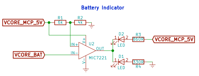
Here’s a link to the circuit to play with: http://everycircuit.com/circuit/6330686118297600.
I think this works, but I don’t know exactly how much power this will draw from the batteries. It’s possible that I might need to use something like a buck converter to make this more efficient. However, if my calculations are correct, it should only be drawing about 0.04~0.05 watts.
Milestone 1
So that’s it, I’m calling the power indicator circuit finished. It may need some more tweaks later, but I think this is a good start. In fact, I think the entire power circuitry is now complete.
Here’s the full schematic update:


You must be logged in to post a comment.